Operation Instructions#
Once you connected the device to the power supply, the system software is started. A detailed description of the commissioning and the adjustment of the software can be found in a separate section.

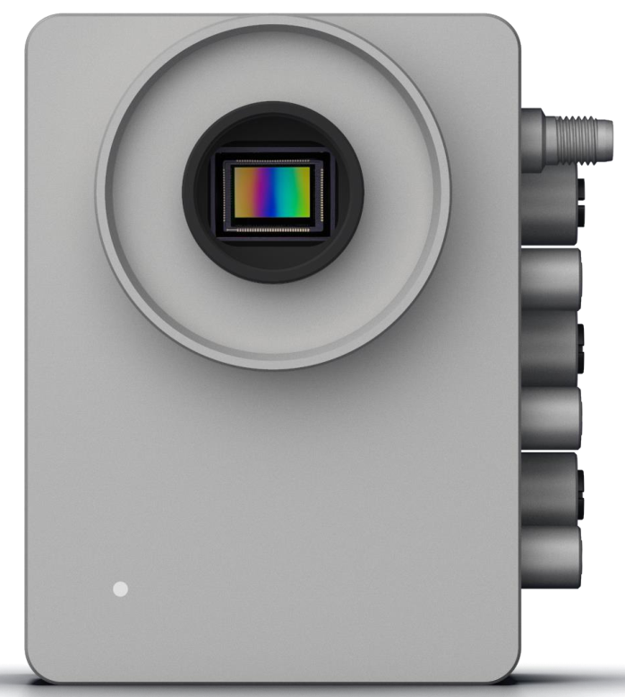
Front side with software status LED on the lower left side (lens side)
Indicators / LED - connector side#
See also general hardware rating
| LED position | LED color | indication |
|---|---|---|
| System status | ||
| (PWR) | blue | Normal operation. |
| Power is connected, system is booting and/or is operating normally. | ||
| (PWR) | red | Reverse current protection active! Error! |
| Connector pins on supply cable are reversed! Turn off the system immediately! | ||
| Please check the connector cable for a possible misconfiguration! | ||
| Ethernet | ||
| (LINK) | green | Continuous or blinking. Normal operation. |
| *Link - Ethernet 1GbE connected. | ||
| (ACT) | yellow | Continuous or blinking. Normal operation. |
| Act - Data transfer active. |
Indicators / LED - front#
See also image above
Note
The front LED is application-controlled and only some Operating-System defined modes can be described here.
| LED color | indication |
|---|---|
| off | normal operation (no application uses LED) |
| blue - flashing | (re-)booting |
| blue | controlled by application running. |
| white | controlled by application running. |
Buttons#
The device can be reset to the factory settings using the reset button. Detailed instructions can be found in the OS section.

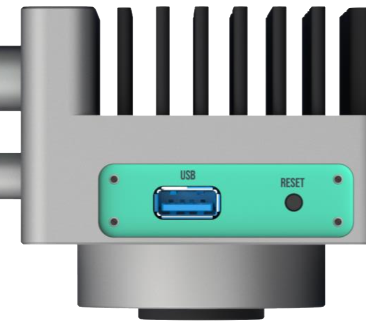
Bottom side of the device, with service cover removed
Note
If the maintenance cover is open, water can get into the device via the USB 3.0 port. Therefore, open the maintenance cover only if you use the USB 3.0 port in a dry environment or for accessing the RESET button.
Remarks#
The device contains no flammable liquids and none potentially toxic or noxious gases.
Danger
If the device is used in a form that is not in accordance with this instructions, the protection supported by the device may be impaired.