Installation of the device#
For mounting, always use the 4 M4 threads on the back of the device and suitable fasteners to ensure a secure hold. The choice of a suitable fastener is at the customer's responsibility. For best performance, mount the device to an aluminum profile to ensure optimal cooling. Make sure that the device is adequately ventilated and/or air circulation around the device is possible. The device is intended for use in dry environments and for indoor use.

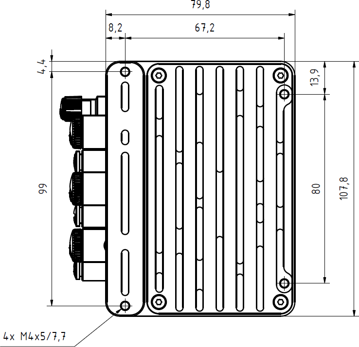
The device must be set up by a qualified person. The device is classified as
a permanently connected device.
The connection to the power supply is established via the port designated "24V DC". The connection cable must be rated for at least 30 V DC / 6 A and must be mandatorily connected to all 4 pins (3 A per pin) of the connector! For example, at an ambient temperature of up to 30°C, the connecting cable shall have a conductor cross-section of 0.21 mm² (corresponds to approx. AWG 22) or higher. Use a sufficient dimensioned power adapter for a supply with DC voltage 24 V ± 10% / 6 A. It is recommended to use a power supply with built-in over-current and over-voltage protection. If no dedicated external power supply is used, an external over-current protection device 8 A fuse (slow acting) should be deployed.
Equipotential Bonding / Protective Earth Connection#
To verify the low-impedance connection of the housing for equipotential bonding, first disconnect all cables from the ECM. With the cables disconnected, measure the resistance of the equipotential bonding path between a screw on the maintenance cover and the equipotential bonding rail.
Use a milliohmmeter with 4-wire measurement capability to determine the resistance of the equipotential bonding path. This value must not exceed 0.1 Ω.
For the equipotential bonding connection, we recommend using a green-yellow grounding cable (4 mm²) with a ring terminal, along with an M4 external-tooth lock washer (DIN 6798-A) made of galvanized spring steel or stainless steel, placed between the ring terminal and the mounting thread. The teeth of the lock washer must penetrate down to the bare metal to establish a permanent connection. This contact area must not be painted, anodized, or otherwise coated. To prevent corrosion of the contact surface, we recommend using contact grease.
Tighten the M4 grounding screw to a torque of 2.4 Nm ±10%.
Use washers at the remaining mounting points to bridge any gap between the camera and the mounting surface. Do not use split lock washers (e.g., DIN 127) to compensate for gaps; these do not have a defined height and do not provide a reliable locking function on aluminum.
Warning
The safety of a system in which the device is integrated lies in the responsibility of the designer/manufacturer of the system!
Warning
To maintain electrical safety, it is mandatory to use an SELV or PELV rated power supply.
Note
We recommend a 10 A fuse as an external over-current protection device (DC) fast acting. External switches, circuit breakers and external over-current protection devices should always be in reach of the installation.
Note
When assembling and connecting the cables, always ensure the correct pin designation according to the plugs and sockets used in conjunction with their respective data sheets.
Note
We recommend checking the low-impedance connection of the housing for equipotential bonding.