Interfaces
General hardware rating#
| Specification | Details | |
|---|---|---|
| Supply voltage range: | 24 V ± 10% DC | |
| current consumption: | stand alone | 2 A |
| continuous lightning | 5.5 A | |
| pulse lightning (DC = 50 %) | 6 A | |
| Power consumption: | maximum | 144 W |
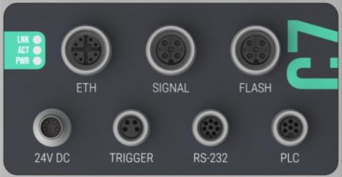
The nominal currents (per pin) and nominal voltages listed below are used by the operator to design the connecting cables. If a signal uses multiple pins (for example, the "24V DC" connection where the GND signal is on pins 2 and 3), both pins must be connected through the cable, and the cable size should be chosen accordingly. Make sure to follow the correct pin assignments!
Power supply#
| Specification | Details |
|---|---|
| Type | M8 male connector |
| Coding | A |
| Number of Pins | 4 |
| Protection class | III |
| Power supply requirements | Safety transformer according to DIN EN 61558-2-6 |
| Cable shield | not required |

| Pin | Function | Parameter | Min | Typ | Max | Unit |
|---|---|---|---|---|---|---|
| 1 | 24 VDC Power Input Port 1 |
Input Voltage | 21.6 | 24 | 26.4 | V |
| Input Current (standalone, without Peripherals) |
1.5 | 2 | A | |||
| rated Current | 3 | A | ||||
| 2 | Ground Power Return Port 2 | |||||
| 3 | Ground Power Return Port 1 | |||||
| 4 | 24 VDC Power Input Port 2 |
Input Voltage | 21.6 | 24 | 26.4 | V |
| rated Current | 3 | A |
Warning
If the current draw of the peripherals powered by the camera exceeds 1 A, a second power supply circuit can be set up using an additional power supply. This results in the following additional requirements:
- separate 2 x 3 A (slow-blow) fuses
- decoupled outputs
- passive/active load balancing
In this case all 4 pins must be connected to the supply line and the socket.
Note
It is possible to supply the Camera standalone with a voltage of 19 V, in this case the PWR_FLASH and PWR_PERI aren't supplied.
Recommended power supplies (among others):
TURCK IM82-24-2.5 (Einzel- und Parallelbetrieb)
TURCK IM82-24-5.0 (Einzel- und Parallelbetrieb)
TURCK PSU67-11-2420/M (Einzel- und Parallelbetrieb)
TURCK PSU67-11-2420/MV (Einzel- und Parallelbetrieb)
TURCK PSU67-11-2440/M (Einzel- und Parallelbetrieb)
Trigger#
| Specification | Details |
|---|---|
| Type | M8 socket |
| Coding | A |
| Number of Pins | 4 |
| Cable shield | required |

| Pin | Function | Parameter | Min | Typ | Max | Unit |
|---|---|---|---|---|---|---|
| 1 | 24 V DC | Output Voltage (Pass through from 24VDC) | 21.6 | 24 | 26.4 | V |
| Output Current (maximum is internal protected) | 0.2 | 1.6 | A | |||
| 2 | Slow Trigger | HIGH State Voltage | 12 | 24 | 30 | V |
| LOW State Voltage | 0 | 1.1 | V | |||
| debouncing cut off frequency | 140 | 150 | 180 | Hz | ||
Software Trigger:
|
||||||
| 3 | Ground | |||||
| 4 | Fast Trigger | HIGH State Voltage | 12 | 24 | 30 | V |
| LOW State Voltage | 0 | 1.1 | V | |||
| debouncing cut off frequency | 4.4 | 5 | 5.5 | MHz | ||
| Hardware Trigger internaly connected to:
|
||||||
Supported peripherals (among others):
Reflection light barrier SICK AG GL6-P4511 (1052634)
Green illuminated pushbutton SIEMENS SIRIUS ACT (3SU1)
RS-232#
| Specification | Details |
|---|---|
| Type | M8 socket |
| Coding | A |
| Number of Pins | 8 |
| Cable shield | required |

| Pin | Function | Parameter | Min | Typ | Max | Unit |
|---|---|---|---|---|---|---|
| 1 | 24 V DC | Output Voltage (Pass through from 24VDC) | 21.6 | 24 | 26.4 | V |
| Output Current (maximum is internal protected) | 0.2 | 1.6 | A | |||
| 2 | Ground | |||||
| 3 | Ground | |||||
| 4 | TxD - Transmit Data Output | Output LOW Voltage | -5.5 | -4.5 | V | |
| Output HIGH Voltage | 4.5 | 5.5 | V | |||
| Output Current | -9 | 9 | mA | |||
| Datarate | 250 | kBit/s | ||||
| 5 | RxD - Receive Data Input | Input LOW Voltage | -25 | -2.7 | V | |
| Input HIGH Voltage | 2.7 | 25 | V | |||
| Input Resistance | 3 | 5 | 7 | kOhm | ||
| Datarate | 250 | kBit/s | ||||
| 6 | Fast Trigger | HIGH State Voltage | 12 | 24 | 30 | V |
| LOW State Voltage | 0 | 1.1 | V | |||
| debouncing cut off frequency | 4.4 | 5 | 5.5 | MHz | ||
| Hardware Trigger internaly connected to:
|
||||||
| 7 | not connected | |||||
| 8 | not connected | |||||
Supported peripherals (among others):
Barcode-scanner SICK CLV620-2120 (1041551)
PLC#
| Specification | Details |
|---|---|
| Type | M8 socket |
| Coding | Amphenol Guided |
| Number of Pins | 6 |
| Cable shield | not required |

| Pin | Function | Parameter | Min | Typ | Max | Unit |
|---|---|---|---|---|---|---|
| 1 | + ISO 1 (DOUT_0)[^1] | rated Voltage | 30 | V | ||
| rated Current | 1.3 | 1.5 | A | |||
| isolated 1-Form-A Normaly Open | ||||||
| 2 | - ISO 1 (DOUT_0)[^1] | return of Pin 1 | ||||
| 3 | + ISO 2 (DOUT_1)[^1] | rated Voltage | 30 | V | ||
| rated Current | 1.3 | 1.5 | A | |||
| isolated 1-Form-A Normaly Open | ||||||
| 4 | + ISO 3 (DOUT_2)[^1] | rated Voltage | 30 | V | ||
| rated Current | 1.3 | 1.5 | A | |||
| isolated 1-Form-A Normaly Open | ||||||
| 5 | - ISO 3 (DOUT_2)[^1] | return of Pin 4 | ||||
| 6 | - ISO 2 (DOUT_1)[^1] | return of Pin 3 | ||||
Compatible Connection Cables
We provide suitable connection cables to ensure reliable integration and performance. These cables are designed with M8-guided 6-pin male connectors to open ends.
The following cable options are available:
| Product Number | Cable Length |
|---|---|
| R20-CC-M8M6G-OE-5 | 5 m |
| R20-CC-M8M6G-OE-10 | 10 m |
| R20-CC-M8M6G-OE-15 | 15 m |
Note
The + and - connections are interchangeable.
Ethernet#


| Specification | Details |
|---|---|
| Type | M12 socket |
| Coding | X |
| Number of Pins | 8 |
| Cable shield | required |
| Pin | Signal 1000BASE-T | Description |
|---|---|---|
| 1 | D1 + | white/orange |
| 2 | D1 - | orange |
| 3 | D2 + | white/green |
| 4 | D2 - | green |
| 5 | D4 + | white/brown |
| 6 | D4 - | brown |
| 7 | D3 - | white/blue |
| 8 | D3 + | blue |
Signal#
| Specification | Details |
|---|---|
| Type | M12 socket |
| Coding | A |
| Number of Pins | 5 |
| Cable shield | required |

| Pin | Function | Parameter | Min | Typ | Max | Unit |
|---|---|---|---|---|---|---|
| 1 | SIGNAL_OUT_0 | Output Voltage (switched from 24V DC) | 21.6 | 24 | 26.4 | V |
| Output Current | 0.2 | 1.6 | A | |||
| 2 | SIGNAL_OUT_2 | Output Voltage (switched from 24V DC) | 21.6 | 24 | 26.4 | V |
| Output Current | 0.2 | 1.6 | A | |||
| 3 | Ground | return | ||||
| 4 | SIGNAL_OUT_3 | Output Voltage (switched from 24V DC) | 21.6 | 24 | 26.4 | V |
| Output Current | 0.2 | 1.6 | A | |||
| 5 | SIGNAL_OUT_1 | Output Voltage (switched from 24V DC) | 21.6 | 24 | 26.4 | V |
| Output Current | 0.2 | 1.6 | A |
Supported peripherals (among others):
-
Pin compatible to WERMA KombiSIGN (71 640.870.00)
-
Eickmann Elektronik MBC-series
- Eickmann Elektronik MB40-series
- LED2WORK SIGNALED II RGB series
- Signal light WERMA CST 60 (696.009.75 AA)
Flash#
| Specification | Details |
|---|---|
| Type | M12 socket |
| Coding | A |
| Number of Pins | 5 |
| Cable shield | required |

| Pin | Function | Parameter | Min | Typ | Max | Unit |
|---|---|---|---|---|---|---|
| 1 | 24VDC Output | Output Voltage (Pass through from 24V DC) | 21.6 | 24 | 26.4 | V |
| Output Current (maximum is internal protected) | 3.5 | 4 | A | |||
| Output Power | 84 | W | ||||
| 2 | FLASH_0 (non-isolated) | Output Voltage (Pass through from 24V DC) | 21.6 | 24 | 26.4 | V |
| Output Current (maximum is internal protected) | 20 | 65 | mA | |||
| 3 | Ground | |||||
| 4 | + FLASH_0 (isolated) | rated Voltage | 2 | 24 | 30 | V |
| rated Current (maximum is internal protected in NPN mode) | 15 | 20 | mA | |||
| 5 | - FLASH_0 (isolated) | return from Pin 4 | ||||
Supported peripherals (among others):
-
PNP

-
NPN

Flashing lights:
Panel lights: